HUS-
V
Screw anc
hor
09
/ 2014
Thes
e pages
are par
t of
the Anchor
Fas
tening
Technology
Man
ual
is
s
ue
September
2014
281
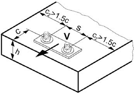
Shear loading
The design shear resistance
is the lower value
of
-
Steel resistance:
V
Rd,s
-
Concrete pryout resistance:
V
Rd,cp
= k
N
Rd,c
-
Concrete edge
resistance:
V
Rd,c
= V
0
Rd,c
f
B
f
ß
f
h
f
4
f
hef
f
c
Basic design shear resistance
Design steel resistance V
Rd,s
Anchor size
HUS-V
8
10
V
Rd,s
[kN]
10,6
13
Design concrete pry-out resistance V
Rd
,c
p
= k
N
Rd,c
a)
Anchor size
HUS-V
8
10
Nominal anchorage
depth
h
nom
[mm]
50
65
55
75
k
1
2
1
2
a)
N
Rd,c
: Design concrete
cone
resistance
Design concrete edge resistance
a)
V
Rd
,c
= V
0
Rd,c
f
B
f
ß
f
h
f
4
f
hef
f
c
Anchor size
HUS-V
8
10
Nominal anchorage
depth
h
nom
[mm]
50
65
55
75
Non-cracked concrete
V
0
Rd,c
[kN]
5,0
5,0
7,2
6,2
Cracked concrete
V
0
Rd,c
[kN]
3,5
3,5
5,1
4,4
d)
For anchor groups
only the anchors close to the edge
must be
considered
,
Influencing factors
Influence of concrete strength
Concrete strength
des
ignation
(ENV 206)
C 20/25
C 25/30
C 30/37
C 35/45
C 40/50
C 45/55
C 50/60
f
B
=
(f
ck,cube
/25N/mm²)
1/2
a)
1
1,1
1,22
1,34
1,41
1,48
1,55
a)
f
ck,cube
= concrete compressive strength, measured
on cubes with 150 mm side lengt
h