Hi
lti
HI
T-R
E 500-SD mortar
wi
th
H
IS-(R)N
sleev
e
Thes
e pages
are part of the Anchor
Fas
tening
Technology Manual is
s
ue September 2014
09 /
2014
522
Setting details
Data according ETA-07/0260,
iss
ue
2013-06-26
Anchor size
M8
M10
M12
M16
M20
Nominal diameter of
drill bit
d
0
[mm]
14
18
22
28
32
Diameter of element
d
[mm]
12,5
16,5
20,5
25,4
27,6
Effectiv
e anchorage
and drill hole depth
h
ef
[mm]
90
110
125
170
205
Minimum base
mate
rial thickne
ss
h
min
[mm]
120
150
170
230
270
Diameter of clearance
hole in the fixture
d
f
[mm]
9
12
14
18
22
Thread engagement
length; min - max
h
s
[mm]
8-20
10-25
12-30
16-40
20-50
Minimum spacing
s
min
[mm]
40
45
55
65
90
Minimum edge
distanc
e
c
min
[mm]
40
45
55
65
90
Critical spacing for
splitting failure
s
cr,sp
2
c
cr,sp
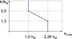
Critical edge
distance
for splitting failure
a)
c
cr,sp
[mm]
1,0
h
ef
for h / h
ef
≥
2,0
4,6 h
ef
-
1,8 h
for 2,0 > h / h
ef
> 1,3
2,26 h
ef
for h / h
ef
≤
1,3
Critical spacing for
concrete cone failure
s
cr,N
2
c
cr,N
Critical edge
distance
for concrete cone
failure
b)
c
cr,N
1,5 h
ef
Torque moment
c)
T
max
[Nm]
10
20
40
80
150
For spacing (edge distanc
e) smaller than critical spacing (critical edge distance) the design loads hav
e to be
reduced.
a)
h: base material
thickness (h
≥
h
min
)
b)
The critical
edge distanc
e for concrete cone failure depends on the embedment depth h
ef
and the design bond
resistance.
The
simplified formula
giv
en
in this table is on the sav
e
side.
c)
This
is
the maximum recommended torque moment t
o av
oid splitting failure during installation for anchors with
minimum spac
ing and/or edge distanc
e.