Hi
lti
HI
T-R
E 500-SD mortar
wi
th HI
T-V ro
d
Thes
e pages
are part of the Anchor
Fas
tening
Technology Manual is
s
ue September 2014
09 /
2014
502
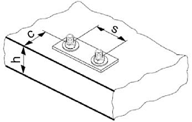
Setting details
Data according ETA-07/0260,
iss
ue
2013-06-26
Anchor size
M8
M10
M12
M16
M20
M24
M27
M30
Nominal diameter of
drill bit
d
0
[mm]
10
12
14
18
24
28
30
35
Effectiv
e anchorage
and drill hole depth
range
a)
h
ef
,min
[mm]
40
40
48
64
80
96
108
120
h
ef
,max
[mm]
160
200
240
320
400
480
540
600
Minimum base
mate
rial thickne
ss
h
min
[mm]
h
ef
+ 30 mm
≥
100 mm
h
ef
+ 2 d
0
Diameter of clearance
hole in the fixture
d
f
[mm]
9
12
14
18
22
26
30
33
Minimum spacing
s
min
[mm]
40
50
60
80
100
120
135
150
Minimum edge
distanc
e
c
min
[mm]
40
50
60
80
100
120
135
150
Critical spacing for
splitting failure
s
cr,sp
2
c
cr,sp
Critical edge
distance
for splitting failure
b)
c
cr,sp
[mm]
1,0
h
ef
for h / h
ef
≥
2,0
4,6 h
ef
-
1,8 h
for 2,0 > h / h
ef
> 1,3
2,26 h
ef
for h / h
ef
≤
1,3
Critical spacing for
concrete cone failure
s
cr,N
2 c
cr,N
Critical edge
distance
for concrete cone
failure
c)
c
cr,N
1,5 h
ef
Torque moment
d)
T
max
[Nm]
10
20
40
80
150
200
270
300
For spacing (edge distance) smaller than critical spac
ing (critical edge distance)
the des
ign loads have
to be
reduced.
a)
h
ef
,min
≤
h
ef
≤
h
ef
,max
(h
ef
: embedment dept
h)
b)
h: base material
thickness (h
≥
h
min
)
c)
The critical
edge distanc
e for concrete cone failure depends on the embedment depth h
ef
and the design bond
resistance.
The
simplified formula
giv
en
in this table is on the s
av
e
side.
d)
This
is
the maximum recommended torque moment t
o av
oid splitting failure during installation for anchors with
minimum spac
ing and/or edge distanc
e.