Hi
lti
HI
T-R
E 500-SD mortar
wi
th
HI
T-
CS(
-
F)
r
od
Thes
e pages
are part of the Anchor
Fas
tening
Technology Manual is
s
ue September 2014
09 /
2014
550
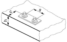
Setting details
Anchor size
M12x110
M16x125
M20x170
Anchor type
HIT-CS-F
HIT-CS
HIT-CS-F
HIT-CS
HIT-CS-F
HIT-CS
Nominal diameter of
drill bit
d
o
[mm]
14
18
22
Cutting diameter of
drill bit
d
cut
≤
[mm]
14,5
18,5
22,5
Effectiv
e anchorage
depth
h
ef
[mm]
102
117
158
Nominal anchorage
depth
h
nom
[mm]
110
125
170
Depth of
drill hole
h
1
≥
[mm]
115
130
175
Minimum base
material thickness
h
min
a)
[mm]
140
170
200
230
250
Diameter of clearance
hole in the
fixture
d
f
≤
[mm]
14
18
22
Minimum spacing and
minimum edge
distanc
e
s
min
[mm]
60
90
80
100
100
120
c
min
[mm]
60
90
80
100
100
120
Critical edge
distance
for splitting failure
s
cr,sp
[mm]
7 hef
7 hef
7 hef
c
cr,sp
[mm]
3,5 hef
3,5 hef
3,5 hef
Critical edge
distance
for concrete cone
failure
s
cr,N
[mm]
330
375
510
c
cr,N
[mm]
165
187,5
255
Max.
torque
moment
T
inst
[Nm]
40
80
150
For spacing (edge distance) smaller than critical spac
ing (critical edge distance)
the des
ign loads have
to be
reduced.
a)
h: base material
thickness (h
≥
h
min
)
Simplified design
method
Simplified v
ersion of t
he
design met
hod
according ETAG 001, Annex C.
Influence
of concrete strength
Influence
of edge distance
Influence
of
spacing
Valid for a group of two anc
hors.
The method may also be applied for anchor groups with more t
han
two
anc
hors or more than one edge distance.
The influencing factors must then be considered for each edge
distanc
e and spacing.
The
design
method
is based on
the following
simplification:
No different
loads are acting on indiv
idual
anchors (no ec
centricity)
The v
alues are v
alid for one anchor.